|
|
Compression Stroke
|
 |
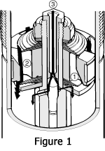
During a compression stroke
path 1, fig 1, is closed, and the oil can only flow through
the paths 2 and 3. The damping forces at a certain compression
speed are determined by the flow restrictions in these paths.
The flow restriction through path 2, fig 1, is determined
by how much the oil pressure can open the compression shims
which are shut close whenever the pressure is too low or the
shock is not moving in a compression mode. These shims resistance
to opening are decided by their numbers, thickness' and diameters.
Path 3, fig 1, is the main bleed valve. The larger orifice,
the less oil flows through path 2 making the main valve compression
forces lower. |
Rebound Stroke
|
 |
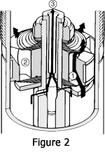
During a rebound stroke path
2, fig 2, is closed and oil can pass through paths 1
and 3.
Damping forces are determined by the flow restriction in paths
1 and 3. The flow restriction through path 1 is
determined by how much the oil pressure can open the rebound
shims which are shut close whenever the pressure is too low
or the shock is not moving in a rebound mode.
The compression and rebound shims are carefully chosen to give
the best setup.
Path 3, fig 2, th the main bleed valve. The larger the
orifice, the less oil flows through path 1 making the
main valve rebound forces lower. |
External Adjusters
|
 |
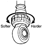
The main bleed valve adjuster,
fig 3, easy to reach on the piston shaft just above the
eyelet, is connected to the valve via an aluminum rod that runs
inside the shaft. When the temperature in the damper increases
the rod expands more than the shaft, closing the bleed adjuster.
This system helps prevent fading caused by loss of oil viscosity
at higher temperatures.
The adjuster affects the low speed damping on both the rebound
and compression. |
|