Compression Damping Cycle
|
1. Compression
cycle
To show you what is happening in an Öhlins TT44 we use the damper
with the 4-way option. The principle illustrated here is the
same for both the basic 3- and the optional 4-way configuration.
Just disregard the poppet valve in the piston shaft and you
will understand how the 3-way configuration works! |
The 3-way configuration stands
for the basic TT44 damper with three external adjusters.
For a start we assume that the adjustable reservoir compression
bleed valve, fig 1E, is fully open. In this case, the
pressure on the compression side of the piston, fig 1G,
will remain almost constant and the same as the gas pressure
during the whole stroke, though some small change of the pressure
will occur because of the change of gas volume caused by shaft
displacement.
As long as the reservoir compression bleed valve is set to fully
open, only the pressure drop on the rebound side of the main
piston, fig 1H, causes the oil to move from the compression
side to the rebound side of the piston.
This means that the initial nitrogen pressure in the reservoir
has to be high enough to handle the compression forces. If the
pressure is too low there is a risk of dumping more oil than
the shaft displaces into the reservoir and the rebound chamber
will not be completely full.
When track conditions cause the vehicle suspension to move,
the damper piston will attempt to move through the damper oil.
In order for the piston to move, oil must flow from one side
of the main piston to the other.
In the initial part of a compression stroke, when the velocity
of the piston is low, the oil flow bypasses the main piston
by travelling through the adjustable low-speed compression bleed
valve, fig 1A, the compression check valve, fig 1B,
and then flows between the two tubes, fig 1C. The oil
re-enters the main tube on rebound side through a port near
the end cap.
As the piston velocity increases the pressure drop across the
main piston will increase. The compression shim stack, fig
1D, depending on the combination of shims, opens at a certain
pressure, providing a direct pathway for the oil, allowing it
to pass through the stack to the other side of the piston.
Observe that it is the pressure drop on the rebound side of
the piston that causes this, not the increase in pressure on
the compression side. Depending on the shim stack, the opening
will be something from abrupt to gradual. A small amount of
oil will always flow through the bleed valve as long as the
piston is moving.
Note: In practice many strokes never reach a velocity
high enough to cause enough pressure drop across the main piston
necessary to cause the shims to open.
During the compression stroke, the oil displaced by the volume
of the piston shaft as it enters the main body is forced into
the reservoir. This causes a small increase in system pressure
due to the piston shaft volume displacement moving the floating
piston and therefore compressing the nitrogen.
In the passage connecting the main body and the reservoir, there
is another compression valve system (one bleed valve in parallel
with a shim stack) similar to the system found in the main body.
By closing off the compression reservoir bleed valve, fig
1E, the reservoir valve system contributes to the total
compression damping.
The reservoir compression bleed valve regulates the flow at
low piston velocities. At higher piston velocities, the reservoir
compression shim stack, fig 1F, opens to provide a pressure
blow-off.
The pressure differential across the main piston will build
up quicker if there is some damping from the reservoir, because
there is not only a pressure drop on the rebound side of the
main piston, but also a pressure rise on the compression side.
Because of the restriction in the reservoir, the pressure in
the whole damper body will rise. This will reduce the risk of
cavitation.
4-way configuration
What has already been described here about the 3-way compression
cycle is still valid with the addition of the "4-way" option,
but now there is also a poppet valve in parallel with the compression
shim stack of the main piston.
The poppet valve is pushed against its seat by a preloaded coil
spring. The amount of preload can be externally adjusted. This
preload determines what pressure differential across the main
piston is necessary to make the poppet valve open.
The 4-way valve provides an additional pathway to the other
side of the piston. The new pathway goes through the centre
of the shaft, fig 1I, and then encounters the 4-way poppet
valve, fig 1J.
As the piston velocity increases the pressure drop across the
main piston rises. At some velocity the movement of the piston
creates a pressure drop across the main piston that equals the
pre-determined pressure required to open the valve. After passing
the valve the oil exits the cross-drilled holes, fig 1K,
in the shaft on the other side of the piston.
Depending on the combination of shim stack and poppet valve
preload, the 4-way valve can open before, at the same time or
after the main piston shim stack. This determines the character
of the damping curve. |
Rebound Damping Cycle
|
2. Rebound
cycle
Again, the principle illustrated here is the same for both the
basic 3- and the optional 4-way configuration. Just disregard
from the poppet valve in the piston shaft and you will understand
how the 3-way configuration works! |
The rebound damping cycle
is the same whether the damper is of 3- or 4-way type.
During the rebound stroke, the pressure of the rebound side
of the main piston is increasing, while the pressure of the
compression side is kept almost constant. This causes the oil
to move back across the piston. When the piston velocity is
low, oil initially will flow between the two tubes, fig 2A,
and arrive at the low-speed rebound bleed valve, fig 2B.
After the valve has metered the flow, the oil will open the
rebound check valve, fig 2C, and travel to the compression
side of the piston.
When the opening pressure of the main piston shim stack is reached,
oil will also pass through the stack, fig 2D.
To compensate for the displacement change caused by the shaft
leaving the body, a check valve in the reservoir, fig 2E,
will open so that oil can return to the compression side of
the piston freely. This will cause a small decrease in system
pressure due to the reduction of piston shaft volume displacement
moving the floating piston and therefore expanding the nitrogen.
4-way configuration
The poppet valve of the 4-way adjuster, fig 2J, has the
function of a check valve. It will seal against the valve seat
during the rebound stroke and therefore prevent oil from flowing
back through the shaft. The oil passage will become identical
to the standard 3-way type damper during the rebound stroke. |
| |
External Damper Adjustmets
|
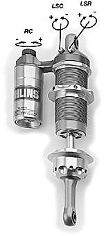
Standard
external adjusters
- = soft. + = hard. |
Optional
high speed compression damping adjuster
- = soft. + = hard. |
The TT44-damper comes
standard as a 3-way externally adjustable damper with
an optional "4-way" adjuster. The adjusters are:
Low-speed compression damping adjuster (LSC)
Type of adjuster: Bleed adjuster.
Affect: The flow from the main piston during compression
strokes only.
Identification: Gold knob at the head of the cylinder
body.
Number of positions: Approximately 38
Low-speed rebound damping adjuster (LSR)
Type of adjuster: Bleed adjuster.
Affect: The flow from the main piston during rebound strokes
only.
Identification: Silver knob at the head of the cylinder
body.
Number of positions: Approximately 38.
Reservoir compression damping adjuster (RC)
Type of adjuster: Bleed adjuster.
Affect: The flow from the displacement of the shaft during
compression strokes only.
Identification: Black knob at the top of the reservoir.
Number of positions: Normally within 20-25. Depends on
the shim stack used.
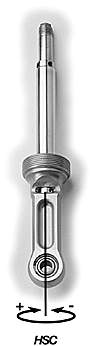
Optional high-speed compression damping adjuster (HSC)
Type of adjuster: Poppet valve preload adjuster.
Affect: The flow from the main piston during compression
strokes only.
Identification: Gold wheel in the end eye.
Number of positions: Approximately 55. |
|
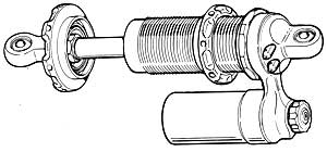
Modular Design
|
The TT44 is designed
for 2 1/4" I.D. springs, but there is also a version for 36
mm I.D. springs (1" I.D. springs can also be used), where the
spring platform is placed on the end cap of the cylinder body.
However after doing some modification, it is possible to fit
some 2" I.D. springs around the cylinder body. Normally the
teams do these modifications themselves.
Note: Reservoir attachment ring as well as the hose attachment
ring rotate and can be mounted at any angle on the cylinder
body.
It is also possible to have reservoir pointing away from shaft
by turning piggyback bracket upside down, if space restrictions
will prevent the conventional mounting. |
|